skip to Main Content

Metal Core PCBs (MCPCBs) Manufacturer

If, even after careful design and layout, your printed circuit board assembly is running hot, you may be required to use a special type of printed circuit board — a metal core PCB, from Rush Flex PCB.

1 Step 1
Get a Free Quote Now

Quantity*:

Lead Time*:

Upload Your Gerber File

reCaptcha v3
keyboard_arrow_leftPrevious
Nextkeyboard_arrow_right

Why Metal Core PCBs?

When printed circuit board components accumulate too much heat, it may lead to their malfunction. Conventional fans are not always adequate to cool electronic devices that generate a considerable amount of heat when operating.

One of the effective alternatives is conductive cooling using metal core boards that provide direct contact between the hot part and the cooler metal part, allowing efficient heat spreading and transfer. This is an effective method, as heat consistently moves to any cooler medium or object.

What is a Metal Core PCB?

Metal Core PCBs are a special type of printed circuit board whose design allows for enhanced thermal management and improved heat dissipation performance. They are also known as insulated metal substrate PCBs.

Unlike regular PCBs of the type FR4, our MCPCBs comprise a metal base layer as the core substrate rather than fiberglass composites. For the metal core, we use common materials like aluminum, copper, and alloy steels. Compared to the fiberglass core, metal cores offer much higher thermal conductivity, enabling effective sinking and spreading of heat away from critical components mounted on the board.

In comparison with regular FR4 boards, our MCPCBs can handle much higher power densities.

In our MCPCBs, the metal core remains insulated from the outer circuit layers. The insulation comes from a layer of directly bonded ceramic dielectric. We use dielectric coatings typically made from beryllium oxide, aluminum nitride, or aluminum oxide.

The selection is based on the thermal conductivity and electrical insulation properties necessary for the application. The insulation layer prevents electrical shorts between the circuit and the core while facilitating effective heat transfer through the base.

Where are Metal Core PCBs Used?

Most LED lighting technologies use our MCPCBs extensively. Moreover, popular applications are in:

  • Motion Control
  • Photovoltaic Cells
  • Solar Panels
  • Voltage Regulators
  • DC-DC Converters
  • Switching Regulators
  • Solid-State Relays
  • Motor Drives
  • Hybrid/Electric Cars
Metal Core PCBs

Difference Between MCPCBs and FR4 PCBs

If you are not satisfied with the heat management on your FR4 PCBs, try our MCPCBs, as these can transfer heat more than 8 times than FR4 boards.

Our MCPCBs keep heat-generating components cooler by removing heat at a much faster rate. We use a very thin dielectric material allowing the shortest path from the hot component to the metal backing. This helps in much quicker heat dissipation.

The dielectric material we use has a typical thickness in the range of 3-6 mils. The major differences between MCPCBs and FR4 PCBs are as follows:

Parameters

MCPCBs

FR4 PCBs (Standard Type)

Thermal Relief

The metal core allows faster heat dissipation. Heat-dissipating vias are not necessary

Heat-dissipating vias essential as the heat transfer rate of PCB is lower.

Thickness

Limited thickness variations. Thickness is governed by metal plate thickness and dielectric material thickness.

Thickness is available in a wide range.

Conductivity

Very high thermal conductivity, typically ranging between 1 and 7 W/mK

Thermal conductivity ranges between 0.3 and 0.4 W/mK.

Component Density

Compact circuit layout, resulting in higher component density.

Vias are necessary to achieve a compact circuit layout, resulting in increased complexity. 

Plated Through Holes

Single layer boards cannot use PTH, all components must be SMC type.

PTH can be implemented.

Machining

Standard machining processes can be used. V-scoring must use a diamond-coated blade, as it has to cut through metal.

Standard machining processes can be used.

Solder mask

Boards meant for LED mounting typically use white solder masks to enhance reflectivity.

May use any color.

Rigidity

The presence of a metal core makes boards 2-4 times stiffer than regular boards, and capable of better handling shock and vibration.

Low rigidity in comparison to metal core boards.

Economy

More expensive because of the metal core.

Less expensive.

Types of MCPCBs from Rush Flex PCB

We commonly use aluminum and copper cores for our MCPCBs.

  • Aluminum Cores

MCPCBs with aluminum cores offer good heat-transferring ability and heat dissipation. As aluminum is light, MCPCBs with aluminum cores are lightweight, and find extensive use in LED lighting, communication electronic equipment, and audio equipment.

Our aluminum core MCPCBs have a typical core thickness between 40 and 120 mils. Of these, 40 and 60 mils are the most common. Characters of our MCPCBs with aluminum substrates are as below:

  • Aluminum thickness — 2-8 mm
  • Thermal Conductivity — 5-20 W/mK
  • Peeling Strength — 9 lb/in
  • Dielectric Loss Angle — 0.03
  • Panel Size — 24” x 18”
  • Flammability — UL94V-0
  • Breakdown Voltage — 3kV+
Metal Core PCBs with aluminum cores offer good heat-transferring ability and heat dissipation.
  • Copper Cores

Our MCPCBs with copper cores offer superior performance compared to aluminum. However, most customers prefer aluminum to copper, as the latter is more expensive.

Moreover, copper is heavy and requires tough machining to process. Additionally, copper corrodes more easily as compared to aluminum.

  • Single-Sided 1-Layer Aluminum MCPCBs

Our single-sided 1-layer aluminum MCPCBs feature an aluminum core with a standard dielectric material. The thermal conductivity of these boards ranges from 1-9 W/mK while being capable of withstanding temperatures of up to 400 °C.

This is the simplest structure that has a single copper layer on the dielectric layer. On these boards, you can assemble only surface mount components on the copper layer.

  • Single-Sided 2-Layer Aluminum MCPCBs

This type of MCPCB has two layers of copper around a single layer of prepreg. However, you can assemble surface mount components only on one of the copper layers. The other layer you can use for routing.

  • Double-Sided 2-Layer Aluminum MCPCBs

This structure is similar to the Single-Sided 1-Layer MCPCB, with the difference that the metal core now has another single-sided layer added on the other side, making it double-sided. Any PTH from one side to the other through the aluminum core is insulated with a resin filling. You can mount components on both sides of the board.

double-sided multi-layer metal core PCBs
  • Double-Sided Multi-Layer Aluminum MCPCBs

Our multi-layer aluminum PCBs are similar to the single-sided 2-layer MCPCBs. The difference is there is an additional single-sided 2-layer on the other side of the metal core.

You can mount surface mount components on the two outermost copper layers, while the inner copper layers are useful for routing. Any through-hole via from one side to the other is insulated from the metal core with resin-filled insulation.


Advantages of Aluminum MCPCBs

Our MCPCBs typically integrate a dielectric polymer layer with high thermal conductivity between the copper layer and an aluminum core. This leads to much lower thermal resistance as compared to regular FR4 boards, offering several advantages as follows:

  • Higher conductivity of the board helps in faster heat transfer
  • Etching the metal core enables control over heat flow away from components
  • Aluminum MCPCBs are lighter than ceramic boards
  • Aluminum cores are long-lasting and offer better heat conduction compared to epoxy products
  • Metal cores are environmentally friendly and recyclable
  • MCPCBs can be implemented in applications with high vibrations, as the core reduces the vibrations.
Advantages of Metal Core PCBS with aluminium core

Manufacturing MCPCBs at Rush Flex PCB

Layers and Bonding

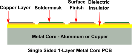
For a typical single-sided 1-layer MCPCB, we first bond the circuit layer of copper foil to the thermally conducting dielectric material layer. Then we bind the dielectric layer to the metal core.

The metal core in the MCPCB is the thickest material on the board. Its thickness depends on the requirements of the application.

Typical thicknesses of the metal core we offer are 1, 1.5, and 3.2 mm. Apart from dissipating heat, the metal layer offers rigidity to the circuit, maintains it flat, and provides adequate thickness to make the circuit compatible with the mounting hardware. We do not coat the exposed metal side of the board with anything like a solder mask or surface finish.

While the dielectric thickness is around 100 µm, the copper foil thickness is typically 1 oz to 10 oz. The main function of the thermally conducting dielectric material layer is to isolate the copper circuit layer from the metal layer while assisting in heat transfer between them.

The dielectric layer effectively disperses the heat from the components to the metal core. Although the higher the thermal conductivity of the dielectric layer, the better will be the heat transfer, but the cost will also increase.

Plated-Through Holes

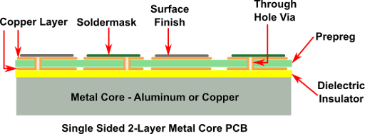
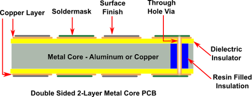
Rush Flex PCB recommends minimizing the use of components requiring plated through holes. This is because the bottom layer being metal, PTH, or NPTH with conductive component leads inserted into it will lead to an electrical short. If PTH components are unavoidable, they must be isolated from the metal core.

We achieve this by drilling the metal core approximately 40-50 mils larger than the PTH dia. Later, we fill them with non-conductive epoxy fillers and then press them.

Once pressing is over, we remove the filler compound from the surface and prepare the boards for lamination with the inner layer cores. After lamination, we drill the plated through holes and the rest of the process is standard.

Regular LED PCBs typically require via-in-pads for proper heat dissipation. This calls for an additional drilling process, making the task more complicated.

Our MCPCBs, with their higher capacity for heat dissipation, do not require via-in-pads, making the manufacturing process simpler.
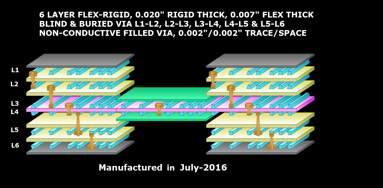
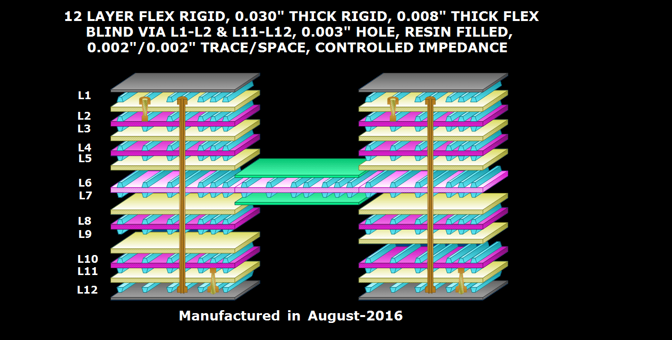
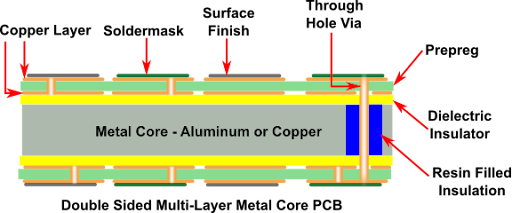
Stackup in MCPCBs

In our double sided pcb and multi-layer MCPCBs, we maintain a symmetrical stackup on either side of the metal core. The number of layers on the top of the core is equal to the layers on the bottom. To avoid warpage issues, we also prefer to maintain copper symmetry just as we do in our standard printed circuit boards.

How MCPCBs Work to Transfer Heat?

Components mounted on a Printed Circuit Board may generate heat during operation. Unless this heat is effectively removed, it can build up and damage the component. As an MCPCBs has a substrate with a high heat transfer coefficient and a metal core backing, the heat from the component can easily transfer to the metal core through the substrate.

The metal core acts as a heat spreader, distributing the heat throughout itself. Any heat sink attached to the metal core can dissipate the heat to the surroundings.

Why Use MCPCBs from Rush Flex PCB?

There are many advantages to using MCPCBs from Rush Flex PCBs. Our MCPCBs allow:

Simpler PCB Design

  • Incorporating both heat sink and circuitry on the same board.
  • Eliminating the need for thermal interface materials and additional heat sinks.
  • Directly soldering components on the board without using insulation pads.
  • Allowing efficient cooling and dense component layouts.
  • Providing enhanced structural rigidity with higher board thickness.

Enhanced Reliability

  • Preventing thermo-mechanical-related stress on components through consistent operating temperatures.
  • Preventing delamination, failures, and micro-cracks typically caused by overheating.
  • Withstanding temperature cycling and higher operating temperatures.
  • Reducing failures, resulting in longer product lifetimes.

Superior Thermal Performance

  • We offer a thick metal core, providing an excellent heat-spreading mechanism for quickly conducting heat away from hot components. This allows effective cooling for power devices and LEDs.
  • We provide an efficient dielectric layer for effective heat transfer from the hot component to the metal core, while electrically isolating the circuit.
  • By effectively reducing the thermal resistance, we offer highly efficient thermal management.


Frequently Asked Questions

Yes. In general, MCPCBs use a metal core, which may be made of copper, steel, or aluminum. An aluminum PCB is a metal core PCB using aluminum as its metal core.

No. The presence of the metal core makes the boards rigid. MCPCBs cannot be flexible.

Yes. We can convert old CAD-generated DWG or DFX files to more sophisticated Gerber files.

Yes, we offer many surface finishes on our MCPCBs. These include ENEPIG, Hard gold, OSP, Lead-Free HASL, HASL, Immersion tin, Immersion silver, and immersion gold.

Layer stacking allows the inclusion of multiple PCBs in the same structure by stacking them one atop the other. We offer multilayer aluminum boards to help our customers achieve speed and functionality in their applications.